2008-08-01
IMPLANTABLE CARDIOVERTER-DEFIBRILLATORS (ICDs)
Implantable cardioverter-defibrillators (ICDs) are surgically implanted devices used to detect and counteract life-threatening, abnormally fast rhythms in the heart’s ventricles.
I. Normal Heart Function
In order to understand the function of ICDs, it is important to understand the abnormal heart rhythms (or arrhythmias) they treat. And, before understanding abnormal heart rhythms, it is first important to become familiar with the basic anatomy and physiology (or function) of the heart.
The heart has four chambers: the top two chambers, called the atria, are relatively small and thin; the bottom two chambers, the ventricles,
are larger and thicker. Blood that has drained from all of the body’s
tissues (except for the lungs) flows through the veins into the right
atrium. The right atriumtricuspid valve and into the right ventricle. The right ventricle then squeezes that blood across the pulmonary valve, through the pulmonary artery and into the lungs. Once in the lungs, the blood is re-supplied with oxygen and continues on its way via the pulmonary veins into the left atrium. The left atrium then contracts, pushing the blood across the mitral valve and into the left ventricle. Finally, the left ventricle squeezes the blood across the aortic valve, through a large artery called the aorta and on to supply the tissues of the body. Note
that the major pumping of blood to sustain life in the body occurs in
the ventricles; therefore, certain severely fast abnormal ventricular
rhythms can lead to death, something the ICD is meant to prevent. then contracts, propelling blood across the
The normal electrical conduction system of the heartThe right and the left sides of the heart actually work simultaneously, so that the atria both contract together, and then the ventricles contract together. These coordinated pumping actions are orchestrated by the heart’s electrical conduction system, and the sinus node can be thought of as the conductor of that orchestra. The sinus node is the normal or physiologic pacemaker. From this structure, which is situated in the upper right atrium, the electrical signal responsible for each heart beat arises. Normally, in response to signals from the brain or the adrenal glands, the sinus node will speed up as needed (such as during exercise, anxiety, or excitement) and slow down when appropriate (such as during rest or sleep).
How does that sinus impulse activate the heart? It is important to understand that the muscle cells of the heart (the same cells responsible for contracting and relaxing the chambers) can conduct electricity from one cell to the next. For example, an electrical signal that starts in one part of the right atria can travel from cell to cell throughout the right atrium and into the left atrium (the right and left atrium are immediately connected and share the same septum or dividing wall). Similarly, an electrical impulse that starts in one ventricle can spread from one ventricle to the other. It is critical to understand this when thinking about the rhythms an ICD will address: if a fast abnormal heart rhythm initiates in just one small part of a ventricle, that muscle cell to muscle cell electrical conduction can result in the spreading of that arrhythmia, such that it can take over the normal rhythm and potentially lead to catastrophic consequences.
Normally, the atria are separated from the ventricles by a fibrous structure which houses the tricuspid and mitral valves, making the two atria electrically disconnected from the two ventricles. In fact, in a normal heart, there is only one way for an electrical signal in the atria to communicate down to the ventricles, and that is via the AV node. The AV node is situated in the middle of the heart, receiving electrical connections from the atria and delivering electrical connections to the ventricles.
When a heart muscle cell is activated by an electrical signal, it contracts. In sum, a normal heart beat arises in the sinus node and propagates across the right atrium and the left atrium via cell to cell electrical connections, resulting in contraction of both atria nearly at the same time. When it reaches the lower atrial septum, it then continues to the AV node. After traveling through the AV node, this electrical signal continues down a network of specialized conduction tissue that spreads the impulse in an organized fashion throughout the ventricles, resulting in an organized contraction of each ventricle nearly simultaneously (Figure 1). The first part of this specialized conduction is the bundle of His, and then the conduction system splits into the right bundle branch (supplying the right ventricle) and the left bundle branch (supplying the left ventricle).

Figure 1.
The normal conduction system of the heart. Yellow arrows demonstrate an
electrical signal originating in the sinus node and propagating through
both the right and left atria. This signal will reach the AV node and
travel through the ventricular conduction system (shown in gold),
ultimately electrically activating the right and left ventricles. The
left atrial appendage, a potential site of blood clot formation in
atrial fibrillation, is also shown. This figure was obtained with
permission from Mr. David Criley at www.blaufuss.org.
II. What are the indications for an implantable cardioverter-defibrillator (ICD)?In general, the purpose of an ICD is to prevent death caused by malignant ventricular arrhythmias. First, to dissect the term “malignant ventricular arrhythmia”: malignant implies potentially lethal. Not all abnormal heart rhythms, even not all abnormal heart rhythms in the ventricle, are potentially lethal. In fact, in many people, a frequent early beat or even several consecutive abnormal beats can be entirely benign or harmless. In general, a malignant ventricular arrhythmia is an abnormal heart rhythm arising from the ventricles that is so fast that the ventricles are incapable of filling with blood and/or pumping blood forward to the extent needed to perfuse the brain and other vital organs. Therefore, such a malignant ventricular arrhythmia can lead to a transient loss of consciousness (also called syncope) if it does not last too long – or death if it lasts long enough. It is important to mention here that the majority of cases of syncope are not related to such arrhythmias, but that an evaluation by a physician is typically required to make this determination. In general terms, there are two types of malignant ventricular arrhythmias: ventricular tachycardia (or VT) and ventricular fibrillation (or VF), which are explained below.
How is the diagnosis of an arrhythmia made?
The majority of the time, an arrhythmia diagnosis is made by an electrocardiogram (ECG). The electrocardiogram involves having several electrodes placed on the body. It is painless and typically takes less than five minutes. With this test, the electrical activity of the heart can be seen: a small wave, called the P wave, corresponds to electrical activation of the atrium during normal sinus rhythm (Figure 2). In a normal rhythm, the larger QRS complex, representing electrical activation of the ventricles, follows shortly after the P wave is inscribed. Such ECG monitoring can be done with what is now the traditional 12 leads (12 stickers on the chest, each with its own wire) in a doctor’s office, emergency department, or the hospital. Such monitoring also can be done with portable/wearable devices at home. Finally, while in the hospital, just a few leads may be attached to a patient’s chest to constantly monitor the heart rhythm during the hospital stay (particularly in intensive care units or cardiac units).

Figure 2.
The electrocardiographic (also called EKG or ECG) recording
demonstrates normal sinus rhythm, with deflections called P waves
(denoted by asterisks) that represent normally conducting atria. Each P
wave is followed by a QRS complex, representing ventricular
depolarization (solid arrows). Each QRS complex is followed by a T wave,
representing repolarization of the ventricles (dashed arrows). Ventricular Tachycardia
Tachycardia generally means a fast heart rate, so ventricular tachycardia (or VT) simply means a fast heart rate originating in one of the ventricles. Whereas ventricular fibrillation (VF) is also a fast rhythm originating in the ventricles (and so technically would fall under the umbrella of the term VT), it has certain characteristics (described below) that make it distinct – therefore, when one talks about VT, the implication is that it is not VF.

 Figure 4. This
is an example of polymorphic ventricular tachycardia in a patient with
abnormal electrical properties in her heart due to certain medicines.
Specifically, this represents a polymorphic ventricular tachycardia
called Torsades de Pointes (or “twisting of the points” in French)
associated with a pathologically abnormal QT interval in the
electrocardiogram. The first beats is a sinus rhythm beat, an early beat
shortly thereafter initiates this fast and wide rhythm where each QRS
looks different from the others; in this particular pattern of Torsades
de Pointes, the axis of the QRS appears to be twisting around itself.
Figure 4. This
is an example of polymorphic ventricular tachycardia in a patient with
abnormal electrical properties in her heart due to certain medicines.
Specifically, this represents a polymorphic ventricular tachycardia
called Torsades de Pointes (or “twisting of the points” in French)
associated with a pathologically abnormal QT interval in the
electrocardiogram. The first beats is a sinus rhythm beat, an early beat
shortly thereafter initiates this fast and wide rhythm where each QRS
looks different from the others; in this particular pattern of Torsades
de Pointes, the axis of the QRS appears to be twisting around itself.
The
details of diagnosing VT on ECG are beyond the scope of this review and
are an important part of the training to become a cardiologist, but one
general concept essentially always applies: because the rhythm is
originating in the ventricles and not down the rapidly conducting,
organized normal conduction system, the QRS is almost always wide (in
other words, the conduction within the ventricles on a given beat occurs
more slowly than it does when activated down the normal special
conduction system). As with many things in medicine, there are always
exceptions, and even VT can have a somewhat narrow QRS, particularly
when it arises from or involves the normal conduction system.
Amongst those with monomorphic VT, there are generally two mechanisms: focal and reentrant. In focal VT, there is a very small piece of ventricular tissue that generates and propagates its own electric signal, firing rapidly, causing a fast ventricular rhythm. Sometimes, this can be encountered in patients with otherwise completely normal hearts (meaning the structure and pumping function of the heart is otherwise normal as detected by imaging studies such as an echocardiogram [an ultrasound of the heart]). In many patients with structurally normal hearts who have these rhythms, an ICD is not indicated because these rhythms are not lethal (remember, the point of the ICD is to prevent death from these rhythms); as these patients may have troublesome symptoms due to this type of VT (such as palpitations, fatigue, and/or shortness of breath), other treatments, such as medicines and/or curative catheter ablation (explained below) may help them considerably.
In reentrant VT, the rhythm is caused by an electrical circuit. Although patients with structurally normal hearts can rarely have such a mechanism for their VT, the majority of cases occur in an abnormal ventricle. Reentry generally occurs when there are two areas in a given part of the heart that have different electrical properties (either differences in the speed of electrical conduction or the speed of electrical recovery after a signal has been conducted – often, these two electrical differences occur together). One of the most common scenarios is a patient who has a scar in the heart from a previous heart attack (or myocardial infarction). One way that reentrant VT can begin in an individual with a scar (or a portion of the heart that does not conduct electrical signals or recover from electrical signals at the same speed as the surrounding tissue) would be from an early beat arising from the ventricle (called a premature ventricular complex, or PVC, something that pretty much everyone has on occasion): after a normal beat, that PVC comes in and electrically conducts at normal speed through one part of tissue, but conducts very slowly through that scar. If the conduction is slow enough through the scar, by the time that conduction exits the scar, it finds the surrounding tissue to be electrically recovered and therefore able to continue to propagate that electrical signal (note that this also has to occur fast enough that the normal conduction from the sinus node and down the normal tissue has not had time to capture the ventricular conduction). In this way, an electrical circuit is set up and can continue (Figure 5).

Tachycardia generally means a fast heart rate, so ventricular tachycardia (or VT) simply means a fast heart rate originating in one of the ventricles. Whereas ventricular fibrillation (VF) is also a fast rhythm originating in the ventricles (and so technically would fall under the umbrella of the term VT), it has certain characteristics (described below) that make it distinct – therefore, when one talks about VT, the implication is that it is not VF.
There
are several ways to categorize VT. To start, it is important to
distinguish monomorphic VT versus polymorphic VT: monomorphic VT means
that all the beats of the VT appear to be the same. This is can be seen
on ECG as every beat of the VT will have an identical QRS during
tachycardia (Figure 3). Polymorphic VT means that each beat looks
different (Figure 4). The distinction between polymorphic VT and VF is
actually often times not so clear (and for the purposes of treating the
condition may not matter).

Figure 3.
Monomorphic ventricular tachycardia in a patient with a prior history
of a myocardial infarction (or heart attack). This ventricular
tachycardia was due to an electrical circuit involving an area of scar
tissue. The black arrows point to 2 QRS complexes. Note that the QRS
complexes are wide because they are originating in the ventricle rather
than through the more organized and rapidly conducting normal conduction
system, and the rhythm is fast or tachycardic
(every small square here is 0.04 milliseconds and each large square is
200 milliseconds, making this rhythm clearly more frequent than every
600 milliseconds and therefore clearly faster than 100 beats per
minute). The morphology of each QRS is the same, making this a
monomorphic ventricular tachycardia.

Amongst those with monomorphic VT, there are generally two mechanisms: focal and reentrant. In focal VT, there is a very small piece of ventricular tissue that generates and propagates its own electric signal, firing rapidly, causing a fast ventricular rhythm. Sometimes, this can be encountered in patients with otherwise completely normal hearts (meaning the structure and pumping function of the heart is otherwise normal as detected by imaging studies such as an echocardiogram [an ultrasound of the heart]). In many patients with structurally normal hearts who have these rhythms, an ICD is not indicated because these rhythms are not lethal (remember, the point of the ICD is to prevent death from these rhythms); as these patients may have troublesome symptoms due to this type of VT (such as palpitations, fatigue, and/or shortness of breath), other treatments, such as medicines and/or curative catheter ablation (explained below) may help them considerably.
In reentrant VT, the rhythm is caused by an electrical circuit. Although patients with structurally normal hearts can rarely have such a mechanism for their VT, the majority of cases occur in an abnormal ventricle. Reentry generally occurs when there are two areas in a given part of the heart that have different electrical properties (either differences in the speed of electrical conduction or the speed of electrical recovery after a signal has been conducted – often, these two electrical differences occur together). One of the most common scenarios is a patient who has a scar in the heart from a previous heart attack (or myocardial infarction). One way that reentrant VT can begin in an individual with a scar (or a portion of the heart that does not conduct electrical signals or recover from electrical signals at the same speed as the surrounding tissue) would be from an early beat arising from the ventricle (called a premature ventricular complex, or PVC, something that pretty much everyone has on occasion): after a normal beat, that PVC comes in and electrically conducts at normal speed through one part of tissue, but conducts very slowly through that scar. If the conduction is slow enough through the scar, by the time that conduction exits the scar, it finds the surrounding tissue to be electrically recovered and therefore able to continue to propagate that electrical signal (note that this also has to occur fast enough that the normal conduction from the sinus node and down the normal tissue has not had time to capture the ventricular conduction). In this way, an electrical circuit is set up and can continue (Figure 5).
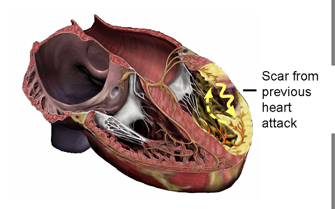
Figure 5.
This image portrays a reentrant ventricular tachycardia involving the
scar from a previous heart attack. This figure was obtained with
permission from Mr. David Criley at www.blaufuss.org.
Because
the circuit continues in the same direction and through the same tissue
at essentially the same speed, the ventricular electrical activation is
the same from one beat to the next in this VT, resulting in the same
morphology QRS in every beat (that is, monomorphic VT as shown in Figure
3). Understanding this mechanism is very helpful in understanding one
way that an ICD can actually painlessly terminate monomorphic VT (and,
as will be discussed below potentially painful therapies, primarily
electrical shocks, from an ICD are always a concern): because
monomorphic VT is typically based on an electrical circuit which is
itself based on the electrical properties of the tissue it traverses,
that VT can be interrupted or broken by placing an early beat (such as a
ventricular beat that arises due to a pacing stimulus from a wire [or lead] placed in the heart); hence, antitachycardia pacing (or ATP,
also discussed below) can effectively terminate VT in some cases. Of
note, ATP generally only works for reentrant and monomorphic VT.
For the purposes of this discussion, polymorphic VT and VF can be thought of as representing a spectrum of the same process. Certainly, with regards to an ICD, the treatment is the same: an electrical shock.
Ventricular Fibrillation (VF) and Polymorphic Ventricular Tachycardia (VT)
Polymorphic VT involves a constantly changing morphology of the QRS. Therefore, it does not represent a stable circuit, but instead typically involves a wandering wave of disorganized and rapid depolarization. Ventricular fibrillation (VF) is essentially an extremely rapid arrhythmia wherein the ventricular tissue is depolarizing in a completely chaotic manner (Figure 6). It can be difficult to tell where polymorphic VT ends and VF begins as any malignant ventricular arrhythmia can degenerate into VF. In fact, either VT or polymorphic VT can lead to loss of perfusion of the tissues and loss of perfusion to the heart (which the heart actually normally supplies via its own normal pumping action), potentially contributing to one common mechanism by which a fast ventricular arrhythmia can lead to complete loss of any organized electrically activity in the heart (VF). Although “VF” implies that there remains some electrical activity (and so it is not the same as a complete cessation of any electrical activity in the heart), it is generally such a chaotic rhythm that it does not result in any forward flow of blood, essentially rendering the heart completely dysfunctional. The name “fibrillation” means that, if one is to look at the heart during VF, the muscles are fibrillating, contracting diffusely in a completely disorganized manner.

In
addition to degeneration from monomorphic VT, polymorphic VT and/or VF
typically occur in patients with significant and usually diffuse or
widespread problems with their ventricular tissue. One example would be a
patient with insufficient blood flow to their heart (such as in the
case of coronary artery disease); in fact, this is likely the cause of sudden death in many people who die during a heart attack. Another
example of those prone to polymorphic VT and VF would be people with a
problem with the way the heart muscle cells handle the ions (such as
calcium, sodium, or potassium) responsible for the normal electrical
conduction and/or electrical recovery of the ventricular tissue. Those
with such electrical problems would include patients who are on
medicines that can effect the electrical conduction of the heart (the
more severe cases typically involving either a person who has an
abnormal metabolism of the medicine, is on multiple medicines that might
effect the potency of one or more toxicities, or are very ill with
multiple other metabolic abnormalities at play). People with electrical
problems in the ventricle that might lead to polymorphic VT or VF would
also include patients with more rare and often inherited syndromes
involving the way that electrical conduction and/or recovery is handled
in the ventricle; this would include the long QT syndrome, the short QT syndrome, the Brugada syndrome, and an entity called catecholaminergic polymorphic VT. A
final general category of those prone to polymorphic VT or VF would be
those with significant structural abnormalities affecting the ventricle
(other than scar from a previous heart attack): this would include
patients with hypertrophic cardiomyopathy (a disorder that is
typically inherited and involves a very thick ventricle with
disorganized muscle fibers in the ventricle) or arrhythmogenic right ventricular dysplasia (also called ARVD,
a disorder that involves an infiltration of heart muscle tissue with
fat and scar tissue, predominantly affecting the right ventricle). Of
note, ARVD may also involve focal VT (which can be monomorphic).
Finally, it is important to mention that this is not an exhaustive list
and that, perhaps more importantly, some people are prone to these
dangerous rhythms for reasons that are as yet unknown. In fact, when
faced with the same stress or injury (such as during a heart attack or
in the face of multiple potentially pro-arrhythmic medicines), some
people appear to be more prone than others. Regardless of the cause and
regardless of whether the issue is a sustained episode of polymorphic VT
or VF, an electrical shock is generally the treatment of choice. The
primary purpose of the ICD is to automatically detect these potentially
lethal arrhythmias, and, when detected, to provide an electrical shock
to restore the heart’s normal rhythm.
Primary Prevention versus Secondary Prevention
The initial studies to show reduced mortality from the use of ICDs were done in patients who had been previously resuscitated from a sudden death episode (generally attributed to a malignant ventricular arrhythmia). 1-5 These subjects were, by definition, undergoing secondary prevention: in other words, they had already manifested the disease to be prevented by the treatment with ICD implantation and so are at very high risk of a malignant ventricular arrhythmia.
III. How is an ICD placed in the body?
Although the first ICDs ever used required a somewhat major operation (such as open heart surgery), the technique now is significantly less invasive. In fact, the majority of the details are identical to those involved in placing a pacemaker (as discussed below), with three major differences: 1) the generator is larger as it has more complex programming and includes the machinery necessary to deliver a high energy shock 2) the wire (or lead) placed in the right ventricle is generally larger in caliber than a typical pacemaker lead and includes one or two coils that enable the conduction of the energy delivered from the generator during the electrical shock and 3) the ability of the device to shock a patient out of VF is typically tested on the patient in a process called defibrillation threshold testing.
The set-up
An ICD will typically be put in by a cardiologist with expertise in the electrical system of the heart such as a cardiac electrophysiologist (also called an EP) in an operating room, cardiac catheterization laboratory (the “cath lab”), or an electrophysiology laboratory (the “EP Lab”). Regardless, the room will be sterile in order to minimize the risk of infection, staffed by nurses and sometimes technicians, with fluoroscopy (or X-ray equipment) available to be positioned over the operating table. The representative from the company manufacturer of the device may
be present.
Patients coming in for this procedure will usually be asked to fast after midnight prior to the day of the procedure (medicines with small sips of water are typically acceptable). Prior to beginning the procedure, an intravenous (or “IV” line) is first placed in the patient and, typically, sedating and relaxing medicines are administered through the IV line. Most often, an anesthesiologist will administer the sedating, relaxing, and anti-pain (analgesic) medicines and may or may not choose to place a breathing tube during the procedure. Prophylactic (preventive) antibiotics are also usually administered in order to minimize the risk of infection. The area of the chest will be cleaned with a solution designed to kill bacteria on the skin, and a sterile drape will be placed over the patient’s body. Typically, ICDs are placed in the left chest, which provides the best direction (or vector) of electrical current to be supplied to the ventricles in the event of an electrical shock. Although more rare, in some circumstances, the device will be placed in the right chest. Of note, the description of this procedure relates to the majority of patients undergoing ICD placement, namely adults without significant congenital heart disease or very unusual anatomy. The nature of the procedure may be quite different in infants and young children or people with either long-standing ICD or pacemaker leads already in place or unusual vascular/heart anatomy.
The pocket
Local anesthetic is given with a small needle in the area where the ICD will be placed. This typically burns when it is first injected, but very quickly becomes numb. Then, the initial incision is made. This is typically about four to six centimeters long and can be made just under the clavicle (collar bone) or at a diagonal, parallel to the groove between the shoulder muscle and the chest. Of note, as with many surgical procedures (if not all), there are subtle differences in technique between operators, and this review is meant to describe the basic concepts of the procedure. After the incision is made, a small “pocket” is then made just under the skin. In some circumstances, the pocket may be made a bit deeper, under the muscle- while a decision to make the pocket “sub-pectoral” (or under the muscle) may be the general preference of the operator, it is typically used with a goal of minimizing any visible bulge under the skin at the site of device placement. The down-side of a sub-pectoral implant is that it may involve more pain and potentially more bleeding. Also, when it comes time to change the battery, the operation can be a bit more involved. Other options for device placement may also be considered, particularly when appearance is a concern; for example, some women will prefer to have the device placed from the side of the chest and under the breast.
The vein and the lead(s)
Subsequently, a vein in the upper arm or upper chest is accessed; again, the technique by which operators access this vein can vary. In some circumstances, the operator will dissect the tissue down to the vessel. More commonly, using known landmarks and a general knowledge of the anatomy of the vein, the operator will introduce a needle on a syringe into the vein. Sometimes, this is facilitated by a peripheral venogram, a procedure where contrast dye that can be visualized under X-ray is injected through an IV in the arm, enabling the operator to see the filling of that vein as blood flows towards the heart. After the vein is accessed with the needle, a floppy wire is placed through the needle and well into the vein. The needle is taken out, leaving the wire in place, and a long plastic tube, termed a sheath, is placed over the wire. The wire is then removed, leaving the sheath in the vein. The sheath has a one-way valve in it, such that blood can not flow from the vein outside, but other long wires or pacemaker leads can be introduced into it from outside. After all of the air has been removed from the sheath by drawing back blood, removing any air, and flushing with fluid, an ICD lead is introduced through the sheath, down the vein, and into the heart under visualization by an X-ray camera (Figure 7).

Figure 7. The ICD lead is a long floppy structure, typically with 1 or 2 coils that facilitate the conduction of the therapeutic electric shock (brackets denote the coils). The figure was obtained with permission from Boston Scientific, Inc. (Natick, MA).
The
somewhat floppy ICD lead has a hole in the middle throughout its
length, allowing for the placement of manually shaped and relatively
stiff stylettes (stiff wires) inside, providing support to the lead and a
means for the operator to steer it into position under X-ray guidance.
In many cases, a second pacemaker lead is placed in the right atrium as
well; this can help with pacing if it is needed for slow heart rates
and, via it’s ability to sense activity in the atrium, can also
help with distinguishing different types of arrhythmias (potentially
helping to prevent an inappropriate shock as discussed below). In
special circumstances, described in the Google knol titled Pacemakers, a third lead may also be placed into a vein called the coronary sinus, enabling biventricular pacing to occur. Note that whether it is just an ICD lead or an atrial pacing lead and an ICD lead, the
right heart chambers are used, primarily because the veins provide
relatively straightforward access to this side of the heart. In
addition, as reviewed in Section I, the venous and right sided heart
chambers do not supply blood directly to the brain; in the worst case
scenario that something should attach itself to a lead (such as a blood
clot or collection of tissue from an infection) and become dislodged, it
is generally preferable that this occur on the right side of the heart
where debris can be caught by the lung rather than on the left side of
the heart where blood flow to the brain could be blocked, potentially
resulting in a stroke.
Once in the position of interest, the leads can be attached to the heart by one of two potential means: active fixation leads have a screw at the tip that is deployed by turning a special wrench at a particular spot on the other end of the lead remaining outside the body; passive fixation leads have special tines on them, allowing them to hook on the many trabeculations (nooks and crannies) present on the inside of the heart (Figure 8). Regardless, it is well understood that the real attachment of the leads requires the patient’s own healing powers. Within approximately one month (although the exact time can vary considerably from one person to the next), the body will scar-down the tip of the leads, fixing them to the inside of the heart.


Figure 9. An example of an ICD generator, with its dimension in millimeters provided. This figure was obtained with permission from St. Jude Medical, Inc. (St. Paul, MN).

Figure 10. The ICD generator is typically placed under the skin in the left chest and the ICD lead is placed via a vein in the left arm, shoulder, or chest into the right ventricle. This figure was obtained with permission from Mr. David Criley at www.blaufuss.org.
Defibrillation Threshold Testing (DFTs)
Although alternative methods to test the device’s function are available and sometimes used, defibrillation threshold testing is typically considered to be the standard of care. First, the patient is sedated heavily and provided analgesics (pain killers) in
anticipation of what would otherwise be a painful electric shock. Then, either a sterile wand connected to a computer is placed over the skin overlying the device so that the computer can communicate with the device, or, in some devices, the computer is able to communicate with the device by wireless remote. Via the computer, functioning of the device and the leads can be assessed. Subsequently, if everything appears to be functioning normally, the device is made to deliver a certain amount of energy during a critically vulnerable part of the electrical cycle in the ventricle so as to induce a malignant ventricular arrhythmia, typically VF. The device is then allowed to detect that arrhythmia: if all is working normally, the right ventricular ICD lead senses the abnormal and fast rhythm in the ventricle, communicating back to the generator. The generator then has an algorithm to deliver an electric shock should that rhythm have certain characteristics, primarily involving the speed of the arrhythmia. Assuming the conditions to shock are met, the generator then delivers a current of energy through the heart using the ICD coils, essentially providing a powerful electric shock to the heart. Typically, this electric shock will terminate VF and normal sinus rhythm will ensue; in other words, the shock will defibrillate the heart.
If the shock fails to defibrillate during the procedure, the patient can typically be defibrillated with the maximum output from the device (particularly as testing will, almost by definition, be performed at an energy level that is at least 10 Joules lower than the maximum output) or from an external defibrillator (via adhesive pads that were placed on the patient prior to the procedure). Clearly, every one of these shocks can be quite painful and therefore the treating physicians will be careful to assure that adequate anesthesia has been provided. In addition, although the risk of an inability to defibrillate is very low, there is a very small chance of death with this procedure. As part of the physician’s assessment prior to the procedure, implantation of this device with DFT testing is generally only recommended when the benefits far outweigh the risks (specifically, that the risk of death without the device far outweighs the risk of death associated with the procedure).
Closing up
After DFT testing is done, any residual bleeding is then typically addressed with cautery (using an instrument that delivers small burns to stop the bleeding) or sutures, and the pocket is then typically washed with an antibiotic and saline solution. The ends of the leads remaining outside the body are then wrapped carefully behind the generator and the generator is placed inside the pocket.
The pocket is then sewn together, typically in several layers to provide strength and a good cosmetic result. For the final layer, some operators will choose to use staples rather than sutures. Many operators will often cover the sutures with special pieces of tape to help with the integrity of the wound as it first heals, and almost all will place a bandage over the wound that is typically removed later that same day or the following morning.
Before going home
A chest X-ray will typically be obtained after the procedure to make sure that the ICD generator and leads remain in appropriate positions and to make sure that there is no evidence of any complications related to the lungs or heart (Figure 11). Typically, the ICD will also be “interrogated.” Similar to the procedure described above just prior to DFT testing, this involves placing a special wand on the skin that overlies the device, enabling communication with a computer. More recently, many devices can be interrogated using wireless technology and a wand is not needed. In either case, via this special computer, the battery life, programming, and integrity of the lead(s) can all be assessed. In most cases, patients will routinely be asked to remain over night and be discharged the following morning (often with a second X-ray and the ICD interrogation that morning to make sure everything remains normal).

Figure 11. A normal chest X-ray after placement of an ICD, showing the ICD generator in the upper left chest and the ICD lead in the right ventricle of the heart. Note the 2 opaque coils along the ICD lead.
Partly to protect the fresh wound and partly because the lead or leads are not initially completely fastened to the heart (as above), the new ICD patient will usually be instructed to restrict movement of the arm on the same side as the ICD for the first week to first month. For example, if the ICD is on the left side, the patient may be instructed to avoid raising the left arm to shoulder level for one week and above shoulder level for one month. Vigorous activity should also generally avoided, particular heavy lifting using the arm on the same side as the device, for at least a week. The patient will also receive instructions regarding wound care, how long the incision needs to remain dry, and any care of remaining tape and/ or bandages. Typically, an appointment to return to the outpatient clinic for a wound check will be made in the first week and often the pacemaker will be interrogated again within the first month.
Risks of the procedure
The risks of the procedure are generally quite low and, as mentioned above, physicians will typically only recommend the procedure if the risks of not having the ICD are greater than the risks involved in procedure itself. As with many aspects of this procedure, the risks are very similar to those that can be encountered during placement of a pacemaker. However, those undergoing ICD placement may, in general, have more cardiovascular disease (which itself is associated with a higher risks of complications), and DFT testing, along with the associated risks, is something unique to ICD placement.
Although the risks are very low, there are several possible complications. For one, if the lung is injured when the needle is introduced into the vein, air may enter into the cavity around the lung (the pleural cavity), resulting in lung collapse or a pneumothorax. Usually, even if this happens, only a small amount of lung is affected (which the patient sometimes does not even notice), and the lung re-inflates itself without any intervention. As discussed above, this is one reason to obtain a chest X-ray after the procedure. If a small pneumothorax (collapse of the lung) is seen, the patient may stay in the hospital for an extra day or two for observation. More rarely, if the lung collapse is more severe or very symptomatic, a chest tube may be placed via the side of the rib cage in order to evacuate the air. Such a chest tube may stay in for a few days, requiring a more prolonged hospital stay.
It is important to understand that the great majority of procedures are done without any complications and that for the great majority of the complications listed above, there are solutions that can be used to address the problem. The treating physician can also counsel patients regarding the individual risks and benefits for a given patient as every situation is different.
IV. What does an implantable cardioverter-defibrillator (ICD) do?
As mentioned above, the purpose of an ICD is to prevent death caused by a dangerously fast ventricular rhythm. The ICD can do this in two ways: most commonly, the ICD provides an electrical shock to the heart, essentially terminating the malignant ventricular arrhythmia such that the normal rhythm of the heart has a chance to take over again (Figure 12). In certain organized ventricular rhythms that are caused by a stable circuit of electrical conduction (as in the case of ventricular tachycardia due to a reentrant electrical pathway through a scar as described above in Section II), anti-tachycardia pacing (or ATP) may be sufficient to terminate the arrhythmia.

Figure 12. Defibrillation of ventricular fibrillation to normal sinus rhythm with an electrical shock. This figure was obtained with permission from Mr. David Criley at www.blaufuss.org.
The first step for the ICD in rendering treatment is of course to detect a dangerous rhythm when it is present. The ICD lead placed in the right ventricle is able to sense the electrical activity of the right ventricle: when electrical activity spreads through the part of the heart where the ICD lead is attached, that change in electrical conduction is detected by the tip of the lead and communicated back to the ICD generator. In the simplest terms, the ICD generator can be programmed to designate a dangerously fast ventricular rhythm as being present if the frequency of electrical signals sensed in the ventricle exceeds a certain programmed interval. For example, a normal heart rate for a given individual may be 50-90 beats a minute at rest and perhaps as fast as 140 beats per minute with exercise. A potentially dangerously fast VT might be as fast as 180 beats per minute and the disorganized chaotic rhythm of VF may be detected at rates of 220 beats a minute or greater. Therefore, the ICD can be programmed to deliver therapy for any ventricular rate greater than 180 beats per minute (or an interval in between electrical signals that would equal that heart rate).
Because delivery of an electric shock from the ICD can be very painful and understandably distressing to patients that experience it, the goal is always to minimize the risk of such a therapy unless absolutely necessary for life-saving purposes. ATP is painless, and works to disrupt a stable electrical circuit by delivering just enough energy at a relatively rapid rate to electrically capture the heart (and therefore pace the heart). If ATP is successful, it will terminate the ventricular tachycardia and the patient’s normal rhythm will take over. While ATP is generally desirable because of its painless effects, it does unfortunately have several drawbacks. First, it is very important to understand that VF or polymorphic VT (as discussed above in Section II) are so disorganized that ATP will not work to terminate them; for these rhythms, only electrical energy in the form of an abrupt shock will work. Second, even during a stable VT, ATP can accelerate the rhythm rather than terminate it, potentially leading to VF or polymorphic VT.
The ICD can be programmed with what are called different zones. For example, a VF zone can be programmed at a certain heart rate, such as greater than 200 beats per minute, and certain therapies will be programmed for that zone. As explained above, ATP will not work for VF, and therefore the therapy will invariably be an electric shock. Different energies to be delivered for that shock as well as the total number of shocks (should a shock fail to terminate the arrhythmia) can also be programmed. That same device can then be programmed with a VT zone, such as for a heart rate of 170-199 beats per minute. If the ICD detects such a heart rate for a pre-programmed period of time, it can be programmed to deliver specific therapies that might differ from those programmed for the VF zone; for example, the VT zone may be programmed with different types of ATP therapy (different types can vary by speed and acceleration and other details beyond the scope of this review), variable numbers of ATP attempts (again, more than one attempt is typically programmed in case the first attempt fails) and then often a number of ICD shocks for that zone should all of the programmed ATP attempts fail.
Note that the numbers given for VT or VF will vary depending on the individual patient and implanting physician. As above, one of the main goals is to have the device provide a shock (which can be very painful) only if it is needed for life saving purposes. Therefore, much of the care of ICD patients is to do everything possible to avoid an inappropriate shock, or to prevent the ICD from delivering a shock for something other than a potentially lethal arrhythmia. For example, the maximum physiologic (or normal) heart rate can vary substantially from patient to patient. One very simple and rough calculation of the maximum predicted heart rate that is often used is 220 minus the patient’s age. Therefore, for an 80 year old patient, the maximum predicted heart rate would roughly be somewhere in the neighborhood of 220-80=140 beats per minute. In that circumstance, one would probably be pretty comfortable programming the ICD to deliver therapies if it detected heart rates above 190 beats per minute (which would likely represent a dangerous rhythm for that particular patient, potentially VT or VF). However, for an 18 year old patient, this same equation would give us a maximum predicted heart rate of 202 beats per minute. This means that, with heavy exercise, this person may normally reach sinus rhythm heart rates (or physiologic heart rates) that are this fast. For this person, if the ICD is programmed to a VF zone of 200 beats per minute or greater, this patient could receive a painful shock while exercising for a rhythm that is completely normal. So why not just program everyone’s VT and VF zones to a very high rate, such as 250 beats per minute? There are several reasons. First, and probably most important, slower rates may still be enough to cause loss of consciousness and/or death, and this may depend largely on the patient’s heart function and underlying total health status. Second, ATP, which is often preferred because it is painless, will only work for stable VT and typically will not work for very fast rates (which typically represent VF); failing to treat a slower VT over a long enough period of time can result in a degeneration to VF, and it is therefore often preferable to first address ventricular arrhythmias with at least an attempt at the painless ATP solution in order to avoid painful shocks. In short, programming these devices represents a balance between risk and benefit and is therefore determined by the implanting physician who will take the individual patient’s characteristics and medical condition into account.
While the delivery of ICD therapies is generally based on heart rates, there are a number of more complicated algorithms that are typically built into the device in an attempt to differentiate malignant ventricular arrhythmias from other more benign rhythms that do not require a shock. Sometimes, placement of the extra lead in the atrium (as above) can help to make these distinctions as sensing the timing of atrial activity may be helpful. Finally, whenever a device detects a rhythm that meets criteria for delivery of therapy, it will store the signals it detected before, during, and after the delivery of therapy. These events can then be reviewed by medical personnel when the device is next interrogated. Therefore, in general, when a patient with an ICD experiences a shock, they are instructed to call their physician. The device can then be checked to make sure the shock was appropriate and, if not, either device reprogramming or other strategies (as described below) can be employed in the hopes of avoiding subsequent inappropriate shocks.
Finally, ICDs generally have all of the same capabilities as a pacemaker. To learn more about that function, there is a separate Google knol on that subject entitled, Pacemakers. Often times, in certain ICD patients with heart failure, a biventricular pacemaker or cardiac resynchronization device will be placed. This also is discussed at the end of the Pacemaker Google knol. In the case of a combined biventricular pacemaker and ICD (often called a biventricular ICD or BiV ICD for short), the ICD leads serves as the right ventricular pacing lead.
V. What kind of care is needed after an ICD is placed?
The immediate care of a new ICD is described above in Section III under Before going home. Otherwise, the only maintenance that is required involves coming in to the local cardiologist’s or cardiac electrophysiologist’s office for regular ICD checks or ICD interrogations. Typically, after the initial few months after implant, these check-ups will be scheduled approximately every three months. However, the exact scheduling may vary considerably from one heart specialist to another.
During these interrogations, a wand is typically placed on the skin overlying the device. This wand is then connected to a computer specific to that ICD manufacturer. Some of the more recently developed devices do not require a wand as the devices can be interrogated using wireless technology (as long as they are in somewhat close proximity). Most cardiac hospital wards and certainly most hospital cardiac device clinics have computers that will be able to recognize ICDs made by each of the different pacemaker companies. Alternatively, as these computers (with their wands) are easily portable, someone from a given device company can also be called to bring the necessary computer if one is not available.
By communicating with the ICD via this computer, the cardiac device nurse, technician, device representative, or physician can do many things. First, the battery can be checked. When only a few months are remaining on the battery life, it is time to schedule a generator change (described below). In addition, the integrity of the leads and the ICD generator can be assessed by running a variety of tests involving assessments of sensing and pacing. Also, the ICD can be reprogrammed as needed to optimize the performance of the device for a given patient (such as the avoidance of inappropriate shocks). Finally, data from the patient’s ICD, such as how fast their heart rate has been, how often they require pacing, the presence of abnormally fast heart rhythms, and potential device therapies can be detected and reviewed.
Some devices have special equipment to allow for ICD interrogations from home, and some of the most recent features can perform such a check up without wires or without having to call the physician’s office. Again, the degree to which these remote interrogations are used varies by a given practitioner, but it is generally well accepted that they may be best suited for those patients that live at great distances and/or for whom frequent travel to the physician’s office is either not feasible or is very inconvenient. Of note, someone (often a nurse or pacemaker technician) still has to review and interpret any data that is sent via these remote checks. With time, these automatic and remote interrogation systems will continue to evolve, with the goal of catching any problems with the ICD well before a scheduled check is due.
The generator change
As mentioned above, ICD interrogations are helpful in providing data on the battery life, and when only several months are remaining on the life of the ICD battery (or generator) it is time to schedule a generator change procedure. The time from initial implant to generator change can vary substantially and depends on several factors: how often a patient is paced, the complexity of the ICD programming, potentially the amount of resistance to each pacing impulse down the pacing lead (which itself may be related to multiple patient and device factors), and the number of therapies that have been delivered. In general, generator changes are required every few years (typically somewhere between four and 10 years, but sometimes more and sometimes less).
This procedure is very much like the initial implantation, but generally a more minor operation. After placing an IV and administering medicines to help the patient relax and prevent general discomfort, the skin over the device is infiltrated with local anesthetic (such as lidocaine or xylocaine). An incision is made over the old device and, using various instruments, such as cautery (the “bovi” that burns tissue), scissors, a scalpel, and others, the original pocket that was made (as described above in Section III) is entered and the ICD generator is removed. The lead or leads attached from that generator are unscrewed and taken out. Typically, the leads are then attached via a cable to the computer so that their function can be directly assessed. If there are any problems with a lead, sometimes a new lead has to be placed. However, in the majority of cases, problems with a lead would have been detected by the regular interrogation described above and, if needed, a lead revision would have been anticipated by the physician and discussed with the patient before the procedure. Assuming no new lead is needed, the inside of the pocket is washed with antibiotic solution. Usually, the pocket will have formed dense scar tissue and some believe that the risk of infection can be reduced if this scar tissue is removed. The lead(s) are then screwed into a new generator, that generator is placed into the pocket, and the pocket and skin are sewn together (again, as described above in Section III). Of note, the new generator is usually not the exact same model as the one that has been removed. Given the time span between initial implant (or previous generator change) and the generator change operation in question, devices will have typically advanced as the technology is essentially always moving forward (Figure 13). One of the more recently available generators (with all of the accompanying new programming and other new features) is compatible with the leads in place and is typically used as the replacement. In addition, if the implanting physician so chooses, the new generator can be chosen from a different company (typically the different device company leads are compatible with different device company’s generators as well).

Figure 13. An example of successive ICD generators made over time by one device company. Note that, despite more sophisticated and complex programming, the newer devices are typically smaller. This figure was obtained with permission from Medtronic, Inc. (Minneapolis, MN).
Just as with the initial procedure, defibrillation threshold testing is usually again performed to make sure the entire system is working appropriately (see Section III).
Because no new leads are placed during the great majority of generator replacements, recovery from the procedure is generally quite quick. Usually, patients will be sent home on the same day after the procedure and a chest X-ray is typically not necessary. Because the leads are generally well fastened given the scarring around them that occurs with time, restrictions on arm movement are usually not as strict as those given after the initial pacemaker implant.
The risks of the procedure depend largely on whether a new lead has to be placed. If a new lead is required, the risks are essentially the same as those described above for an initial ICD implant (Section III). One risk that is likely higher for the generator change procedure than it is for the initial implant (regardless of whether new leads are placed or not) is the risk of infection. Probably because the pocket has a relatively poor blood supply given the natural scarring that occurs with healing and time, the immune cells that can fight infection may not be as readily available to the new generator as they were when the pocket was first made. In the hopes of preventing infection, most physicians will prescribe prophylactic antibiotics for several days after a generator change procedure (in addition to the IV antibiotics routinely given during the operation).
VI. What kind of problems might be encountered due to an ICD?
An inappropriate shock
As discussed and somewhat interwoven into Section IV, an ICD patient may experience an inappropriate shock. This can occur for a variety of reasons and can be both painful and significantly distressing to the patient that experiences it. Because the primary method of detecting a potentially dangerous rhythm relies on the ICD lead detection of a fast ventricular rate, anything (dangerous or not) that might result in a fast ventricular rate might be the cause of an inappropriate shock. One important consideration is the highest rate a given patient’s heart may achieve during heavy exertion as part of normal activity. While this peak heart rate may depend on age, fitness of the patient, underlying disease, and medicines (among other things), the implanting physician ultimately decides on the parameters used to program the device. In addition to a very fast physiologic rhythm, other abnormal rhythms can result in an inappropriate shock. For example, somewhat common arrhythmias arising from the atrial chambers (such as atrial fibrillation or atrial flutter) can result in a fast ventricular response without being lethal, and, if detected in the programmed VT or VF zone by the ICD can result in a shock that is not needed for life-saving purposes. Fortunately, interrogation of the device after such an episode can often demonstrate that such rhythms were the cause and therapies (such as adding certain medicines or using percutaneous ablation procedures) can then be used to prevent future episodes. Another cause of an inappropriate shock might be a problem with the ICD lead, such as a fracture that causes the inappropriate sensing of very fast electrical signals. Finally, electromagnetic interference (discussed below) can result in an inappropriate shock.
While many efforts are made to minimize the risk of an inappropriate shock before the device is even placed, it is very important for all ICD patients to at least be aware that this is a possibility. For this reason, ICDs are not typically thought of as devices that help improve quality of life. Instead, as has been emphasized throughout this review, the goal of the placement of an ICD is to prolong life. This is very important when selecting appropriate patients for the placement of these devices and in counseling them with regards to their individual goals of care (which, for example, might differ substantially between the otherwise healthy 20 year old with the long QT syndrome and the 100 year old person with heart failure). Also, as above, should these inappropriate shocks occur, there are several strategies that can be employed (most in a non-invasive fashion) to reduce the risks of inappropriate shocks in the future.
An appropriate shock
While an appropriate shock is generally a very good thing in that it generally is a life saving event, it nonetheless can be very painful. Often, as in the case of inappropriate shocks, such an event can result in significant anxiety regarding the possibility of future shocks. While some patients may experience a single appropriate shock on such a rare basis that no change in management is required, others may experience such frequent events that they experience an unacceptable degree of suffering. Usually, even after a single shock, a device interrogation will be performed and methods will be employed to help reduce the chance of another shock. The nature of the methods used will depend largely on the type of arrhythmia detected by the device. Often times, the addition of certain medicines may be helpful. A change in the device programming may help (particularly if the painless use of ATP can be used as an effective substitute for the shock). A procedure called catheter ablation can be a very effective method of eradicating some ventricular arrhythmias. Briefly, this involves using special catheters placed into the heart via veins and/or arteries (typically entering from the leg) under X-ray guidance. Once there, either the trigger for the arrhythmias or more commonly the critical substrate responsible for an electric circuit can be targeted and destroyed, typically with the use of radiofrequency energy (Figure 14). In some circumstances, treating the underlying heart disease (such as by opening up a closed blood vessel or optimizing therapy for heart failure) can help reduce the risk of subsequent dangerous events.

Figure 14. The left side of the figure demonstrates ventricular tachycardia due to en electrically circuit through a scar due to a previous myocardial infarction (or MI). On the right, a catheter is used to deliver radiofrequency energy to burn (or ablate) the critical portion of that circuit, eradicate the arrhythmia and prevent it from occurring. This figure was obtained with permission from Mr. David Criley at www.blaufuss.org.
Device Recalls
A full discussion of device recalls and all of their implications is beyond the scope of this review. However, while they are generally uncommon, they are important enough to mention here. It must be understood that as can happen with any machine, ICDs can develop unanticipated problems. In fact, all device companies have had recalls of their pacemakers and/or ICDs at one time or another. Sometimes, the problem is in the generator, sometimes the problem is in the lead. The severity of the recall also varies: some problems can be fixed with a simple software upgrade (via the computer in a non-invasive fashion) and others require a surgical procedure for replacement. Fortunately, on the whole, these recalls are rare, but patients with ICDs should realize that a device recall (as with any complex device) is a possibility.
Electromagnetic Interference
Electromagnetic interference (EMI) is essentially any high powered electric or magnetic signal that is sensed by a cardiac device.12 Fortunately, given the improved shielding of commonly used devices as well as an improvement in the way modern ICDs are made, EMI with the ICD is quite rare. For example, modern microwave machines are not a problem around modern ICDs. However, it is important to understand what EMI can do and to be familiar with common sources of EMI that might be encountered. An exhaustive list will not be provided here, but the cardiac device technician or nurse that performs the ICD interrogation at regular intervals and/or the representative from the company that makes a particular device are good resources for this information.
As mentioned above, EMI generally does not permanently damage ICDs, but tends to wreak havoc only while it is present. However, very powerful electromagnetic fields can theoretically permanently affect an ICD. One example of this is magnetic resonance imaging (MRI) that might be indicated to image a certain part of the body for medical reasons. The MRI can damage the ICD and may even result in dangerous rhythms by a direct influence on the ICD lead. While research in this area is on-going, generally ICD patients should not undergo MRI scans. The decision to consider an MRI might be made by the treating physicians if the risk-benefit ratio favors performing the scan, and this would generally be a decision made after discussions between the treating physician and the electrophysiology/ ICD expert and certainly between the physicians and the patient.
Other resources:
Other sources of information related to ICDs can be found at several sites, including reviews and guideline recommendations provided by the American Heart Association, American College of Cardiology, and the Heart Rhythm Society):
For general guidelines related to cardiac devices (pacemakers and ICDs):
http://www.americanheart.org/downloadable/heart/1032981283481CleanPacemakerFinalFT.pdf
For the purposes of this discussion, polymorphic VT and VF can be thought of as representing a spectrum of the same process. Certainly, with regards to an ICD, the treatment is the same: an electrical shock.
Ventricular Fibrillation (VF) and Polymorphic Ventricular Tachycardia (VT)
Polymorphic VT involves a constantly changing morphology of the QRS. Therefore, it does not represent a stable circuit, but instead typically involves a wandering wave of disorganized and rapid depolarization. Ventricular fibrillation (VF) is essentially an extremely rapid arrhythmia wherein the ventricular tissue is depolarizing in a completely chaotic manner (Figure 6). It can be difficult to tell where polymorphic VT ends and VF begins as any malignant ventricular arrhythmia can degenerate into VF. In fact, either VT or polymorphic VT can lead to loss of perfusion of the tissues and loss of perfusion to the heart (which the heart actually normally supplies via its own normal pumping action), potentially contributing to one common mechanism by which a fast ventricular arrhythmia can lead to complete loss of any organized electrically activity in the heart (VF). Although “VF” implies that there remains some electrical activity (and so it is not the same as a complete cessation of any electrical activity in the heart), it is generally such a chaotic rhythm that it does not result in any forward flow of blood, essentially rendering the heart completely dysfunctional. The name “fibrillation” means that, if one is to look at the heart during VF, the muscles are fibrillating, contracting diffusely in a completely disorganized manner.

Figure 6. An
example of normal sinus rhythm followed by the rapid and chaotic
ventricular activity indicative of ventricular fibrillation (or VF) is
shown. This figure was obtained with permission from Mr. David Criley at
www.blaufuss.org.
Primary Prevention versus Secondary Prevention
The initial studies to show reduced mortality from the use of ICDs were done in patients who had been previously resuscitated from a sudden death episode (generally attributed to a malignant ventricular arrhythmia). 1-5 These subjects were, by definition, undergoing secondary prevention: in other words, they had already manifested the disease to be prevented by the treatment with ICD implantation and so are at very high risk of a malignant ventricular arrhythmia.
The problem is that the great majority of malignant ventricular arrhythmias actually occur in people without a prior history.4, 6, 7
Therefore, a major goal of many large studies has been to determine
which patients without a previous malignant arrhythmia are at a
sufficiently high risk such that they would benefit from the
prophylactic (protective) insertion of an ICD; these patients would be
said to be undergoing primary prevention (they have not yet
manifested the disease the treatment with an ICD is meant to address).
After a progression of very large and well designed randomized
controlled clinical trials, the primary indication that has consistently
been found to indicate a high enough risk so as to warrant placement of
an ICD has to do with a measure of the pumping function of the heart
called the ejection fraction (or EF).3, 8-11 When
the EF is significantly low and the potential for improvement within a
relatively short period of time is also reasonably low, an ICD may be
indicated. Examples where a low EF might improve (and therefore negate
the need for an ICD) would be in some who undergo revascularization of
blocked blood vessels or those who undergo appropriate effective heart
failure medical therapy. Unfortunately, the EF is not a perfect measure,
and it is well known that many patients with a low EF may never have a
malignant ventricular arrhythmia and many patients with a normal or only
mildly reduced EF may still die of such an arrhythmia. Ongoing research
is assessing other potential measures to predict these arrhythmias in
order to either add to or replace the use of the EF alone as the main
predictor.
It
needs to be mentioned that while the majority of ICDs implanted are done
so in this primary prevention population with a significantly low EF,
there are several much more rare syndromes (such as the long QT
syndrome, the short QT syndrome, the Brugada syndrome, catecholaminergic
polymorphic VT, arrhythmogenic right ventricular dysplasia, and
hypertrophic cardiomyopathy, all mentioned above) that may also
themselves be appropriate indications for a primary prevention ICD
(independent of EF).4 In general, the risk of sudden death
due to a malignant ventricular arrhythmia needs to be assessed for each
individual with one of these syndromes, and whether or not a patient
should be considered for an ICD ultimately comes from an evaluation by a
cardiologist trained specifically in the treatment of arrhythmias (such
as a cardiac electrophysiologist). III. How is an ICD placed in the body?
Although the first ICDs ever used required a somewhat major operation (such as open heart surgery), the technique now is significantly less invasive. In fact, the majority of the details are identical to those involved in placing a pacemaker (as discussed below), with three major differences: 1) the generator is larger as it has more complex programming and includes the machinery necessary to deliver a high energy shock 2) the wire (or lead) placed in the right ventricle is generally larger in caliber than a typical pacemaker lead and includes one or two coils that enable the conduction of the energy delivered from the generator during the electrical shock and 3) the ability of the device to shock a patient out of VF is typically tested on the patient in a process called defibrillation threshold testing.
The set-up
An ICD will typically be put in by a cardiologist with expertise in the electrical system of the heart such as a cardiac electrophysiologist (also called an EP) in an operating room, cardiac catheterization laboratory (the “cath lab”), or an electrophysiology laboratory (the “EP Lab”). Regardless, the room will be sterile in order to minimize the risk of infection, staffed by nurses and sometimes technicians, with fluoroscopy (or X-ray equipment) available to be positioned over the operating table. The representative from the company manufacturer of the device may
be present.
Patients coming in for this procedure will usually be asked to fast after midnight prior to the day of the procedure (medicines with small sips of water are typically acceptable). Prior to beginning the procedure, an intravenous (or “IV” line) is first placed in the patient and, typically, sedating and relaxing medicines are administered through the IV line. Most often, an anesthesiologist will administer the sedating, relaxing, and anti-pain (analgesic) medicines and may or may not choose to place a breathing tube during the procedure. Prophylactic (preventive) antibiotics are also usually administered in order to minimize the risk of infection. The area of the chest will be cleaned with a solution designed to kill bacteria on the skin, and a sterile drape will be placed over the patient’s body. Typically, ICDs are placed in the left chest, which provides the best direction (or vector) of electrical current to be supplied to the ventricles in the event of an electrical shock. Although more rare, in some circumstances, the device will be placed in the right chest. Of note, the description of this procedure relates to the majority of patients undergoing ICD placement, namely adults without significant congenital heart disease or very unusual anatomy. The nature of the procedure may be quite different in infants and young children or people with either long-standing ICD or pacemaker leads already in place or unusual vascular/heart anatomy.
The pocket
Local anesthetic is given with a small needle in the area where the ICD will be placed. This typically burns when it is first injected, but very quickly becomes numb. Then, the initial incision is made. This is typically about four to six centimeters long and can be made just under the clavicle (collar bone) or at a diagonal, parallel to the groove between the shoulder muscle and the chest. Of note, as with many surgical procedures (if not all), there are subtle differences in technique between operators, and this review is meant to describe the basic concepts of the procedure. After the incision is made, a small “pocket” is then made just under the skin. In some circumstances, the pocket may be made a bit deeper, under the muscle- while a decision to make the pocket “sub-pectoral” (or under the muscle) may be the general preference of the operator, it is typically used with a goal of minimizing any visible bulge under the skin at the site of device placement. The down-side of a sub-pectoral implant is that it may involve more pain and potentially more bleeding. Also, when it comes time to change the battery, the operation can be a bit more involved. Other options for device placement may also be considered, particularly when appearance is a concern; for example, some women will prefer to have the device placed from the side of the chest and under the breast.
The vein and the lead(s)
Subsequently, a vein in the upper arm or upper chest is accessed; again, the technique by which operators access this vein can vary. In some circumstances, the operator will dissect the tissue down to the vessel. More commonly, using known landmarks and a general knowledge of the anatomy of the vein, the operator will introduce a needle on a syringe into the vein. Sometimes, this is facilitated by a peripheral venogram, a procedure where contrast dye that can be visualized under X-ray is injected through an IV in the arm, enabling the operator to see the filling of that vein as blood flows towards the heart. After the vein is accessed with the needle, a floppy wire is placed through the needle and well into the vein. The needle is taken out, leaving the wire in place, and a long plastic tube, termed a sheath, is placed over the wire. The wire is then removed, leaving the sheath in the vein. The sheath has a one-way valve in it, such that blood can not flow from the vein outside, but other long wires or pacemaker leads can be introduced into it from outside. After all of the air has been removed from the sheath by drawing back blood, removing any air, and flushing with fluid, an ICD lead is introduced through the sheath, down the vein, and into the heart under visualization by an X-ray camera (Figure 7).

Figure 7. The ICD lead is a long floppy structure, typically with 1 or 2 coils that facilitate the conduction of the therapeutic electric shock (brackets denote the coils). The figure was obtained with permission from Boston Scientific, Inc. (Natick, MA).
Once in the position of interest, the leads can be attached to the heart by one of two potential means: active fixation leads have a screw at the tip that is deployed by turning a special wrench at a particular spot on the other end of the lead remaining outside the body; passive fixation leads have special tines on them, allowing them to hook on the many trabeculations (nooks and crannies) present on the inside of the heart (Figure 8). Regardless, it is well understood that the real attachment of the leads requires the patient’s own healing powers. Within approximately one month (although the exact time can vary considerably from one person to the next), the body will scar-down the tip of the leads, fixing them to the inside of the heart.
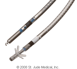
Figure 8. This
figure demonstrates an active fixation ICD lead (top), with the screw
deployed. On the bottom, a passive fixation ICD lead with tines on the
end is shown. This image is provided with permission from St. Jude
Medical Inc. (St. Paul, MN).
Once
the lead or leads are in position, they are tested electronically to
make sure they are working well. They are then secured by suture to the
floor of the pocket that has been made. The ends are then plugged into
the ICD generator. Once the lead or leads have been plugged into the
generator, they are secured there with a special screw. The ICD
generator includes the battery and the computer, with all of the ICD
programming (Figure 9). The leads are then wrapped carefully behind the
generator and the generator is placed into the pocket that was made
previously. Figure 10 demonstrates the general appearance of an ICD
generator and a single ICD lead.Figure 9. An example of an ICD generator, with its dimension in millimeters provided. This figure was obtained with permission from St. Jude Medical, Inc. (St. Paul, MN).

Figure 10. The ICD generator is typically placed under the skin in the left chest and the ICD lead is placed via a vein in the left arm, shoulder, or chest into the right ventricle. This figure was obtained with permission from Mr. David Criley at www.blaufuss.org.
Defibrillation Threshold Testing (DFTs)
Although alternative methods to test the device’s function are available and sometimes used, defibrillation threshold testing is typically considered to be the standard of care. First, the patient is sedated heavily and provided analgesics (pain killers) in
anticipation of what would otherwise be a painful electric shock. Then, either a sterile wand connected to a computer is placed over the skin overlying the device so that the computer can communicate with the device, or, in some devices, the computer is able to communicate with the device by wireless remote. Via the computer, functioning of the device and the leads can be assessed. Subsequently, if everything appears to be functioning normally, the device is made to deliver a certain amount of energy during a critically vulnerable part of the electrical cycle in the ventricle so as to induce a malignant ventricular arrhythmia, typically VF. The device is then allowed to detect that arrhythmia: if all is working normally, the right ventricular ICD lead senses the abnormal and fast rhythm in the ventricle, communicating back to the generator. The generator then has an algorithm to deliver an electric shock should that rhythm have certain characteristics, primarily involving the speed of the arrhythmia. Assuming the conditions to shock are met, the generator then delivers a current of energy through the heart using the ICD coils, essentially providing a powerful electric shock to the heart. Typically, this electric shock will terminate VF and normal sinus rhythm will ensue; in other words, the shock will defibrillate the heart.
However,
the purpose of this test (or these DFT tests) are to make sure that the
device adequately senses and can shock the heart out of this fast and
potentially lethal rhythm (see below for an explanation of what is done
if the test should fail.) Of note, although the term “defibrillation
threshold test” continues to be used, it is actually not an accurate
description of this procedure. The term is a remnant of previous
practice, during which multiple inductions of malignant arrhythmias,
each followed by shocks of different energies, were performed for the
purpose of determining the actual energy threshold at which successful
defibrillation would occur. The primary goal of current practice is to
demonstrate a 10 Joule safety margin, ideally on two consecutive
tests: as the energy delivered by the device is measured in Joules, this
means that a successful defibrillation should be demonstrated at a
level at least 10 Joules below the total energy the device is able to
deliver. For example, if a device can deliver, at most, 35 Joules, the
test will be considered successful if defibrillation can be accomplished
with 25 Joules. The lower the energy that can successfully
defibrillate, the better. Ultimately, these tests help to determine the
probability of a successful shock when it is really needed during the
spontaneous initiation of one of these potentially lethal arrhythmias,
and the implanting physician makes the decision regarding the risk
versus benefit of whether or not to do these tests at all, the level of
energy used during the test, and the numbers of tests performed.
If
the first test does not successfully defibrillate with the goal 10
Joule safety margin, several strategies can be employed to make sure
that the safety margin is ultimately achieved: changing the ICD lead
position or changing the direction or nature of the energy waveform can
help. If needed, an extra energy-conducting coil (often called a subcutaneous array)
is placed under the skin and around the back (behind the heart), in
order to provide a more ideal vector (or path) for the defibrillating
energy. If the shock fails to defibrillate during the procedure, the patient can typically be defibrillated with the maximum output from the device (particularly as testing will, almost by definition, be performed at an energy level that is at least 10 Joules lower than the maximum output) or from an external defibrillator (via adhesive pads that were placed on the patient prior to the procedure). Clearly, every one of these shocks can be quite painful and therefore the treating physicians will be careful to assure that adequate anesthesia has been provided. In addition, although the risk of an inability to defibrillate is very low, there is a very small chance of death with this procedure. As part of the physician’s assessment prior to the procedure, implantation of this device with DFT testing is generally only recommended when the benefits far outweigh the risks (specifically, that the risk of death without the device far outweighs the risk of death associated with the procedure).
Closing up
After DFT testing is done, any residual bleeding is then typically addressed with cautery (using an instrument that delivers small burns to stop the bleeding) or sutures, and the pocket is then typically washed with an antibiotic and saline solution. The ends of the leads remaining outside the body are then wrapped carefully behind the generator and the generator is placed inside the pocket.
The pocket is then sewn together, typically in several layers to provide strength and a good cosmetic result. For the final layer, some operators will choose to use staples rather than sutures. Many operators will often cover the sutures with special pieces of tape to help with the integrity of the wound as it first heals, and almost all will place a bandage over the wound that is typically removed later that same day or the following morning.
Before going home
A chest X-ray will typically be obtained after the procedure to make sure that the ICD generator and leads remain in appropriate positions and to make sure that there is no evidence of any complications related to the lungs or heart (Figure 11). Typically, the ICD will also be “interrogated.” Similar to the procedure described above just prior to DFT testing, this involves placing a special wand on the skin that overlies the device, enabling communication with a computer. More recently, many devices can be interrogated using wireless technology and a wand is not needed. In either case, via this special computer, the battery life, programming, and integrity of the lead(s) can all be assessed. In most cases, patients will routinely be asked to remain over night and be discharged the following morning (often with a second X-ray and the ICD interrogation that morning to make sure everything remains normal).

Figure 11. A normal chest X-ray after placement of an ICD, showing the ICD generator in the upper left chest and the ICD lead in the right ventricle of the heart. Note the 2 opaque coils along the ICD lead.
Partly to protect the fresh wound and partly because the lead or leads are not initially completely fastened to the heart (as above), the new ICD patient will usually be instructed to restrict movement of the arm on the same side as the ICD for the first week to first month. For example, if the ICD is on the left side, the patient may be instructed to avoid raising the left arm to shoulder level for one week and above shoulder level for one month. Vigorous activity should also generally avoided, particular heavy lifting using the arm on the same side as the device, for at least a week. The patient will also receive instructions regarding wound care, how long the incision needs to remain dry, and any care of remaining tape and/ or bandages. Typically, an appointment to return to the outpatient clinic for a wound check will be made in the first week and often the pacemaker will be interrogated again within the first month.
Risks of the procedure
The risks of the procedure are generally quite low and, as mentioned above, physicians will typically only recommend the procedure if the risks of not having the ICD are greater than the risks involved in procedure itself. As with many aspects of this procedure, the risks are very similar to those that can be encountered during placement of a pacemaker. However, those undergoing ICD placement may, in general, have more cardiovascular disease (which itself is associated with a higher risks of complications), and DFT testing, along with the associated risks, is something unique to ICD placement.
Although the risks are very low, there are several possible complications. For one, if the lung is injured when the needle is introduced into the vein, air may enter into the cavity around the lung (the pleural cavity), resulting in lung collapse or a pneumothorax. Usually, even if this happens, only a small amount of lung is affected (which the patient sometimes does not even notice), and the lung re-inflates itself without any intervention. As discussed above, this is one reason to obtain a chest X-ray after the procedure. If a small pneumothorax (collapse of the lung) is seen, the patient may stay in the hospital for an extra day or two for observation. More rarely, if the lung collapse is more severe or very symptomatic, a chest tube may be placed via the side of the rib cage in order to evacuate the air. Such a chest tube may stay in for a few days, requiring a more prolonged hospital stay.
Bleeding
at the site is also a risk. Usually, because the pocket provides some
pressure and constriction to any blood that might build up, the risk
here is generally not related to blood loss per se. However, such a
build up of blood and clot (called a pocket hematoma) can be very
uncomfortable and also can increase the risk for infection. Sometimes,
this type of bleeding occurs in the setting of blood thinning medicines
that a patient needs to take for other reasons (such as a mechanical
heart valve or atrial fibrillation), and the decision to withhold versus
continue those blood thinning agents is made by the treating physician
in the hopes of maximizing benefit and minimizing harm.
Another
risk is infection, which is why the procedure is done under sterile
conditions and antibiotics are typically administered during – and often
after – the operation. Infection may occur through the skin site, and
may not show itself for a long period of time. After an ICD has been in
place, an infection from a different source that is traveling in the
blood can also attach itself to the leads. Note that these infections
are typically severe bacterial or fungal infections (in other words, not
a common virus like the typical cold or flu). While antibiotics are
part of the treatment of an ICD infection, removal of the pacemaker and
leads is typically also necessary. As noted above, due to the fixation
of the leads to the heart by the bodies healing process that occurs over
time, ICD extraction can sometimes be difficult and poses additional
risks.
Another
rare but significant complication that can occur during the procedure
involves a perforation of the heart: if one of the leads pokes a hole in
the heart, bleeding can occur outside the heart, collect in the sack
that lines the heart (the pericardium), and constrict the heart.
This can be life threatening and the treatment involves an emergency
evacuation of the blood with a needle placed under the rib cage. The
hole will seal itself, and a drain placed into that pericardial space may have to remain in place for a few days. This requires that the patient stay in the hospital until the tube is removed.
As
mentioned above, the unique complication related to ICD placement (as
opposed to a pacemaker placement) is the risk that the VF induced for
the purposes of DFT testing can not be defibrillated. If this occurs,
the procedure can result in death. Fortunately, this is very rare and,
as mentioned, above, external defibrillation pads are always placed on a
patient prior to inducing VF. While such a complication can not always
be predicted, some patients are known to be at higher risk than others:
for example, patients with severe coronary artery disease (where the
coronary arteries are obstructed due to a build up of cholesterol
plaques) that have not been revascularized (such as with angioplasty,
stenting, or surgery) may be at higher risk; patients with severely
depressed function of the heart, particularly those with very large
hearts of unknown cause (sometimes called idiopathic or non-ischemic
cardiomyopathy) also appear to be at higher risk. As mentioned above,
the decision to pursue DFT testing, the nature of those tests, and the
number of tests are ultimately up to the implanting physician who will
weigh the pros and cons of each option. Importantly, it can be argued
that these high risk patients are also those in whom one would want to
make sure the device is working, not only because they may be at the
highest risk of having a dangerous arrhythmia, but also because one
would want to be more convinced that the device is working appropriately
– that the leads are in optimal position, that a subcutaneous array is
or is not needed, and that the direction of the energy is correct. It is important to understand that the great majority of procedures are done without any complications and that for the great majority of the complications listed above, there are solutions that can be used to address the problem. The treating physician can also counsel patients regarding the individual risks and benefits for a given patient as every situation is different.
IV. What does an implantable cardioverter-defibrillator (ICD) do?
As mentioned above, the purpose of an ICD is to prevent death caused by a dangerously fast ventricular rhythm. The ICD can do this in two ways: most commonly, the ICD provides an electrical shock to the heart, essentially terminating the malignant ventricular arrhythmia such that the normal rhythm of the heart has a chance to take over again (Figure 12). In certain organized ventricular rhythms that are caused by a stable circuit of electrical conduction (as in the case of ventricular tachycardia due to a reentrant electrical pathway through a scar as described above in Section II), anti-tachycardia pacing (or ATP) may be sufficient to terminate the arrhythmia.

Figure 12. Defibrillation of ventricular fibrillation to normal sinus rhythm with an electrical shock. This figure was obtained with permission from Mr. David Criley at www.blaufuss.org.
The first step for the ICD in rendering treatment is of course to detect a dangerous rhythm when it is present. The ICD lead placed in the right ventricle is able to sense the electrical activity of the right ventricle: when electrical activity spreads through the part of the heart where the ICD lead is attached, that change in electrical conduction is detected by the tip of the lead and communicated back to the ICD generator. In the simplest terms, the ICD generator can be programmed to designate a dangerously fast ventricular rhythm as being present if the frequency of electrical signals sensed in the ventricle exceeds a certain programmed interval. For example, a normal heart rate for a given individual may be 50-90 beats a minute at rest and perhaps as fast as 140 beats per minute with exercise. A potentially dangerously fast VT might be as fast as 180 beats per minute and the disorganized chaotic rhythm of VF may be detected at rates of 220 beats a minute or greater. Therefore, the ICD can be programmed to deliver therapy for any ventricular rate greater than 180 beats per minute (or an interval in between electrical signals that would equal that heart rate).
Because delivery of an electric shock from the ICD can be very painful and understandably distressing to patients that experience it, the goal is always to minimize the risk of such a therapy unless absolutely necessary for life-saving purposes. ATP is painless, and works to disrupt a stable electrical circuit by delivering just enough energy at a relatively rapid rate to electrically capture the heart (and therefore pace the heart). If ATP is successful, it will terminate the ventricular tachycardia and the patient’s normal rhythm will take over. While ATP is generally desirable because of its painless effects, it does unfortunately have several drawbacks. First, it is very important to understand that VF or polymorphic VT (as discussed above in Section II) are so disorganized that ATP will not work to terminate them; for these rhythms, only electrical energy in the form of an abrupt shock will work. Second, even during a stable VT, ATP can accelerate the rhythm rather than terminate it, potentially leading to VF or polymorphic VT.
The ICD can be programmed with what are called different zones. For example, a VF zone can be programmed at a certain heart rate, such as greater than 200 beats per minute, and certain therapies will be programmed for that zone. As explained above, ATP will not work for VF, and therefore the therapy will invariably be an electric shock. Different energies to be delivered for that shock as well as the total number of shocks (should a shock fail to terminate the arrhythmia) can also be programmed. That same device can then be programmed with a VT zone, such as for a heart rate of 170-199 beats per minute. If the ICD detects such a heart rate for a pre-programmed period of time, it can be programmed to deliver specific therapies that might differ from those programmed for the VF zone; for example, the VT zone may be programmed with different types of ATP therapy (different types can vary by speed and acceleration and other details beyond the scope of this review), variable numbers of ATP attempts (again, more than one attempt is typically programmed in case the first attempt fails) and then often a number of ICD shocks for that zone should all of the programmed ATP attempts fail.
Note that the numbers given for VT or VF will vary depending on the individual patient and implanting physician. As above, one of the main goals is to have the device provide a shock (which can be very painful) only if it is needed for life saving purposes. Therefore, much of the care of ICD patients is to do everything possible to avoid an inappropriate shock, or to prevent the ICD from delivering a shock for something other than a potentially lethal arrhythmia. For example, the maximum physiologic (or normal) heart rate can vary substantially from patient to patient. One very simple and rough calculation of the maximum predicted heart rate that is often used is 220 minus the patient’s age. Therefore, for an 80 year old patient, the maximum predicted heart rate would roughly be somewhere in the neighborhood of 220-80=140 beats per minute. In that circumstance, one would probably be pretty comfortable programming the ICD to deliver therapies if it detected heart rates above 190 beats per minute (which would likely represent a dangerous rhythm for that particular patient, potentially VT or VF). However, for an 18 year old patient, this same equation would give us a maximum predicted heart rate of 202 beats per minute. This means that, with heavy exercise, this person may normally reach sinus rhythm heart rates (or physiologic heart rates) that are this fast. For this person, if the ICD is programmed to a VF zone of 200 beats per minute or greater, this patient could receive a painful shock while exercising for a rhythm that is completely normal. So why not just program everyone’s VT and VF zones to a very high rate, such as 250 beats per minute? There are several reasons. First, and probably most important, slower rates may still be enough to cause loss of consciousness and/or death, and this may depend largely on the patient’s heart function and underlying total health status. Second, ATP, which is often preferred because it is painless, will only work for stable VT and typically will not work for very fast rates (which typically represent VF); failing to treat a slower VT over a long enough period of time can result in a degeneration to VF, and it is therefore often preferable to first address ventricular arrhythmias with at least an attempt at the painless ATP solution in order to avoid painful shocks. In short, programming these devices represents a balance between risk and benefit and is therefore determined by the implanting physician who will take the individual patient’s characteristics and medical condition into account.
While the delivery of ICD therapies is generally based on heart rates, there are a number of more complicated algorithms that are typically built into the device in an attempt to differentiate malignant ventricular arrhythmias from other more benign rhythms that do not require a shock. Sometimes, placement of the extra lead in the atrium (as above) can help to make these distinctions as sensing the timing of atrial activity may be helpful. Finally, whenever a device detects a rhythm that meets criteria for delivery of therapy, it will store the signals it detected before, during, and after the delivery of therapy. These events can then be reviewed by medical personnel when the device is next interrogated. Therefore, in general, when a patient with an ICD experiences a shock, they are instructed to call their physician. The device can then be checked to make sure the shock was appropriate and, if not, either device reprogramming or other strategies (as described below) can be employed in the hopes of avoiding subsequent inappropriate shocks.
Finally, ICDs generally have all of the same capabilities as a pacemaker. To learn more about that function, there is a separate Google knol on that subject entitled, Pacemakers. Often times, in certain ICD patients with heart failure, a biventricular pacemaker or cardiac resynchronization device will be placed. This also is discussed at the end of the Pacemaker Google knol. In the case of a combined biventricular pacemaker and ICD (often called a biventricular ICD or BiV ICD for short), the ICD leads serves as the right ventricular pacing lead.
V. What kind of care is needed after an ICD is placed?
The immediate care of a new ICD is described above in Section III under Before going home. Otherwise, the only maintenance that is required involves coming in to the local cardiologist’s or cardiac electrophysiologist’s office for regular ICD checks or ICD interrogations. Typically, after the initial few months after implant, these check-ups will be scheduled approximately every three months. However, the exact scheduling may vary considerably from one heart specialist to another.
During these interrogations, a wand is typically placed on the skin overlying the device. This wand is then connected to a computer specific to that ICD manufacturer. Some of the more recently developed devices do not require a wand as the devices can be interrogated using wireless technology (as long as they are in somewhat close proximity). Most cardiac hospital wards and certainly most hospital cardiac device clinics have computers that will be able to recognize ICDs made by each of the different pacemaker companies. Alternatively, as these computers (with their wands) are easily portable, someone from a given device company can also be called to bring the necessary computer if one is not available.
By communicating with the ICD via this computer, the cardiac device nurse, technician, device representative, or physician can do many things. First, the battery can be checked. When only a few months are remaining on the battery life, it is time to schedule a generator change (described below). In addition, the integrity of the leads and the ICD generator can be assessed by running a variety of tests involving assessments of sensing and pacing. Also, the ICD can be reprogrammed as needed to optimize the performance of the device for a given patient (such as the avoidance of inappropriate shocks). Finally, data from the patient’s ICD, such as how fast their heart rate has been, how often they require pacing, the presence of abnormally fast heart rhythms, and potential device therapies can be detected and reviewed.
Some devices have special equipment to allow for ICD interrogations from home, and some of the most recent features can perform such a check up without wires or without having to call the physician’s office. Again, the degree to which these remote interrogations are used varies by a given practitioner, but it is generally well accepted that they may be best suited for those patients that live at great distances and/or for whom frequent travel to the physician’s office is either not feasible or is very inconvenient. Of note, someone (often a nurse or pacemaker technician) still has to review and interpret any data that is sent via these remote checks. With time, these automatic and remote interrogation systems will continue to evolve, with the goal of catching any problems with the ICD well before a scheduled check is due.
The generator change
As mentioned above, ICD interrogations are helpful in providing data on the battery life, and when only several months are remaining on the life of the ICD battery (or generator) it is time to schedule a generator change procedure. The time from initial implant to generator change can vary substantially and depends on several factors: how often a patient is paced, the complexity of the ICD programming, potentially the amount of resistance to each pacing impulse down the pacing lead (which itself may be related to multiple patient and device factors), and the number of therapies that have been delivered. In general, generator changes are required every few years (typically somewhere between four and 10 years, but sometimes more and sometimes less).
This procedure is very much like the initial implantation, but generally a more minor operation. After placing an IV and administering medicines to help the patient relax and prevent general discomfort, the skin over the device is infiltrated with local anesthetic (such as lidocaine or xylocaine). An incision is made over the old device and, using various instruments, such as cautery (the “bovi” that burns tissue), scissors, a scalpel, and others, the original pocket that was made (as described above in Section III) is entered and the ICD generator is removed. The lead or leads attached from that generator are unscrewed and taken out. Typically, the leads are then attached via a cable to the computer so that their function can be directly assessed. If there are any problems with a lead, sometimes a new lead has to be placed. However, in the majority of cases, problems with a lead would have been detected by the regular interrogation described above and, if needed, a lead revision would have been anticipated by the physician and discussed with the patient before the procedure. Assuming no new lead is needed, the inside of the pocket is washed with antibiotic solution. Usually, the pocket will have formed dense scar tissue and some believe that the risk of infection can be reduced if this scar tissue is removed. The lead(s) are then screwed into a new generator, that generator is placed into the pocket, and the pocket and skin are sewn together (again, as described above in Section III). Of note, the new generator is usually not the exact same model as the one that has been removed. Given the time span between initial implant (or previous generator change) and the generator change operation in question, devices will have typically advanced as the technology is essentially always moving forward (Figure 13). One of the more recently available generators (with all of the accompanying new programming and other new features) is compatible with the leads in place and is typically used as the replacement. In addition, if the implanting physician so chooses, the new generator can be chosen from a different company (typically the different device company leads are compatible with different device company’s generators as well).

Figure 13. An example of successive ICD generators made over time by one device company. Note that, despite more sophisticated and complex programming, the newer devices are typically smaller. This figure was obtained with permission from Medtronic, Inc. (Minneapolis, MN).
Just as with the initial procedure, defibrillation threshold testing is usually again performed to make sure the entire system is working appropriately (see Section III).
Because no new leads are placed during the great majority of generator replacements, recovery from the procedure is generally quite quick. Usually, patients will be sent home on the same day after the procedure and a chest X-ray is typically not necessary. Because the leads are generally well fastened given the scarring around them that occurs with time, restrictions on arm movement are usually not as strict as those given after the initial pacemaker implant.
The risks of the procedure depend largely on whether a new lead has to be placed. If a new lead is required, the risks are essentially the same as those described above for an initial ICD implant (Section III). One risk that is likely higher for the generator change procedure than it is for the initial implant (regardless of whether new leads are placed or not) is the risk of infection. Probably because the pocket has a relatively poor blood supply given the natural scarring that occurs with healing and time, the immune cells that can fight infection may not be as readily available to the new generator as they were when the pocket was first made. In the hopes of preventing infection, most physicians will prescribe prophylactic antibiotics for several days after a generator change procedure (in addition to the IV antibiotics routinely given during the operation).
VI. What kind of problems might be encountered due to an ICD?
An inappropriate shock
As discussed and somewhat interwoven into Section IV, an ICD patient may experience an inappropriate shock. This can occur for a variety of reasons and can be both painful and significantly distressing to the patient that experiences it. Because the primary method of detecting a potentially dangerous rhythm relies on the ICD lead detection of a fast ventricular rate, anything (dangerous or not) that might result in a fast ventricular rate might be the cause of an inappropriate shock. One important consideration is the highest rate a given patient’s heart may achieve during heavy exertion as part of normal activity. While this peak heart rate may depend on age, fitness of the patient, underlying disease, and medicines (among other things), the implanting physician ultimately decides on the parameters used to program the device. In addition to a very fast physiologic rhythm, other abnormal rhythms can result in an inappropriate shock. For example, somewhat common arrhythmias arising from the atrial chambers (such as atrial fibrillation or atrial flutter) can result in a fast ventricular response without being lethal, and, if detected in the programmed VT or VF zone by the ICD can result in a shock that is not needed for life-saving purposes. Fortunately, interrogation of the device after such an episode can often demonstrate that such rhythms were the cause and therapies (such as adding certain medicines or using percutaneous ablation procedures) can then be used to prevent future episodes. Another cause of an inappropriate shock might be a problem with the ICD lead, such as a fracture that causes the inappropriate sensing of very fast electrical signals. Finally, electromagnetic interference (discussed below) can result in an inappropriate shock.
While many efforts are made to minimize the risk of an inappropriate shock before the device is even placed, it is very important for all ICD patients to at least be aware that this is a possibility. For this reason, ICDs are not typically thought of as devices that help improve quality of life. Instead, as has been emphasized throughout this review, the goal of the placement of an ICD is to prolong life. This is very important when selecting appropriate patients for the placement of these devices and in counseling them with regards to their individual goals of care (which, for example, might differ substantially between the otherwise healthy 20 year old with the long QT syndrome and the 100 year old person with heart failure). Also, as above, should these inappropriate shocks occur, there are several strategies that can be employed (most in a non-invasive fashion) to reduce the risks of inappropriate shocks in the future.
An appropriate shock
While an appropriate shock is generally a very good thing in that it generally is a life saving event, it nonetheless can be very painful. Often, as in the case of inappropriate shocks, such an event can result in significant anxiety regarding the possibility of future shocks. While some patients may experience a single appropriate shock on such a rare basis that no change in management is required, others may experience such frequent events that they experience an unacceptable degree of suffering. Usually, even after a single shock, a device interrogation will be performed and methods will be employed to help reduce the chance of another shock. The nature of the methods used will depend largely on the type of arrhythmia detected by the device. Often times, the addition of certain medicines may be helpful. A change in the device programming may help (particularly if the painless use of ATP can be used as an effective substitute for the shock). A procedure called catheter ablation can be a very effective method of eradicating some ventricular arrhythmias. Briefly, this involves using special catheters placed into the heart via veins and/or arteries (typically entering from the leg) under X-ray guidance. Once there, either the trigger for the arrhythmias or more commonly the critical substrate responsible for an electric circuit can be targeted and destroyed, typically with the use of radiofrequency energy (Figure 14). In some circumstances, treating the underlying heart disease (such as by opening up a closed blood vessel or optimizing therapy for heart failure) can help reduce the risk of subsequent dangerous events.

Figure 14. The left side of the figure demonstrates ventricular tachycardia due to en electrically circuit through a scar due to a previous myocardial infarction (or MI). On the right, a catheter is used to deliver radiofrequency energy to burn (or ablate) the critical portion of that circuit, eradicate the arrhythmia and prevent it from occurring. This figure was obtained with permission from Mr. David Criley at www.blaufuss.org.
Device Recalls
A full discussion of device recalls and all of their implications is beyond the scope of this review. However, while they are generally uncommon, they are important enough to mention here. It must be understood that as can happen with any machine, ICDs can develop unanticipated problems. In fact, all device companies have had recalls of their pacemakers and/or ICDs at one time or another. Sometimes, the problem is in the generator, sometimes the problem is in the lead. The severity of the recall also varies: some problems can be fixed with a simple software upgrade (via the computer in a non-invasive fashion) and others require a surgical procedure for replacement. Fortunately, on the whole, these recalls are rare, but patients with ICDs should realize that a device recall (as with any complex device) is a possibility.
Electromagnetic Interference
Electromagnetic interference (EMI) is essentially any high powered electric or magnetic signal that is sensed by a cardiac device.12 Fortunately, given the improved shielding of commonly used devices as well as an improvement in the way modern ICDs are made, EMI with the ICD is quite rare. For example, modern microwave machines are not a problem around modern ICDs. However, it is important to understand what EMI can do and to be familiar with common sources of EMI that might be encountered. An exhaustive list will not be provided here, but the cardiac device technician or nurse that performs the ICD interrogation at regular intervals and/or the representative from the company that makes a particular device are good resources for this information.
Some
examples of modern-day sources of EMI include cell phones (in
particular situations as below), arc-welding devices, and security
devices such as those encountered at the airport. Many other potential
sources of EMI are found in the hospital and involve other procedures
(such as lithotripsy, electroconvulsive therapy, electrical
cardioversions, and magnetic resonance imaging [MRI]). Fortunately, in
all of these cases, a physician is involved and will help make decisions
as well as communicate with the heart specialist responsible for a
patient’s ICD care. Because they are relatively common and are true
sources of particularly strong EMI, MRI machines are discussed briefly
below.
There are
generally three concerns regarding a device encountering EMI: potential
damage to the device, interference with pacing, and a resultant
inappropriate shock. Damage to the device is quite rare and requires
very powerful EMI (such as with an MRI scan as below). Problems with the
pacing function of the device are discussed in the Google knol
entitled, Pacemakers.
EMI
as a cause of an inappropriate shock will be discussed here. The
concern is that, if an electromagnetic signal is detected by an ICD,
that ICD generally has no way of knowing that the signal originates from
somewhere outside the patient’s heart. Therefore, it may interpret this
outside signal as intrinsic heart activity. Commonly, these signals are
interpreted as very rapid activity, potentially meeting criteria for
delivery of ICD therapies. One example is the metal detector/security
device we all walk through at the airport or the wand that is sometimes
used by airport personnel. Both of these devices emit EMI. If one walks
through and does not linger under the detector, there is typically not
enough time for the EMI to result in a sufficiently long duration of the
detection of the rapid signals to result in a shock. Similarly, if the
wand is swept over the area of the device, a fraction of a second of EMI
should generally not be long enough to cause a shock. However, if an
ICD patient stood under the metal detector for long enough, persistent
rapid electrical activity might be detected by the ICD for a long enough
duration so as to activate ICD therapies.
Cell
phones are generally not felt to emit sufficient energy to result in
significant EMI when carried at a reasonable distance from the ICD.
However, it is generally recommended that they not be carried in a
pocket directly over the device. The strongest signal is thought to
occur just when the cell phone is called, and, if a cell is called while
it is sitting in a pocket directly over the device, it could result in
significant EMI. Arc-welding is mentioned above simply because it
reliably results in significant EMI and therefore ICD patients should
generally avoid being near that activity.As mentioned above, EMI generally does not permanently damage ICDs, but tends to wreak havoc only while it is present. However, very powerful electromagnetic fields can theoretically permanently affect an ICD. One example of this is magnetic resonance imaging (MRI) that might be indicated to image a certain part of the body for medical reasons. The MRI can damage the ICD and may even result in dangerous rhythms by a direct influence on the ICD lead. While research in this area is on-going, generally ICD patients should not undergo MRI scans. The decision to consider an MRI might be made by the treating physicians if the risk-benefit ratio favors performing the scan, and this would generally be a decision made after discussions between the treating physician and the electrophysiology/ ICD expert and certainly between the physicians and the patient.
Other resources:
Other sources of information related to ICDs can be found at several sites, including reviews and guideline recommendations provided by the American Heart Association, American College of Cardiology, and the Heart Rhythm Society):
For general guidelines related to cardiac devices (pacemakers and ICDs):
http://www.americanheart.org/downloadable/heart/1032981283481CleanPacemakerFinalFT.pdf
For guidelines related to dangerous ventricular arrhythmias:
http://circ.ahajournals.org/cgi/reprint/114/10/e385
For guidelines related to patients with heart failure:
http://circ.ahajournals.org/cgi/content/full/112/12/e154 The Heart Rhythm Society has a website dedicated to the treatment of abnormal heart rhythms (at www.hrsonline.org). Patient pages from this site can be found directly at http://www.hrspatients.org/patients/signs_symptoms/default.asp
To learn more about the treatment of arrhythmias at the University of California, San Francisco (UCSF), please visit www.ucsfhealth.org/arrhythmia
To learn more about the treatment of arrhythmias at the University of California, San Francisco (UCSF), please visit www.ucsfhealth.org/arrhythmia
References
1. Kuck
KH, Cappato R, Siebels J, Ruppel R. Randomized comparison of
antiarrhythmic drug therapy with implantable defibrillators in patients
resuscitated from cardiac arrest : the Cardiac Arrest Study Hamburg
(CASH). Circulation. 2000;102(7):748-754.
2. A
comparison of antiarrhythmic-drug therapy with implantable
defibrillators in patients resuscitated from near-fatal ventricular
arrhythmias. The Antiarrhythmics versus Implantable Defibrillators
(AVID) Investigators. N Engl J Med. 1997;337(22):1576-1583.
3. Gregoratos
G, Abrams J, Epstein AE, Freedman RA, Hayes DL, Hlatky MA, Kerber RE,
Naccarelli GV, Schoenfeld MH, Silka MJ, Winters SL, Gibbons RJ, Antman
EM, Alpert JS, Gregoratos G, Hiratzka LF, Faxon DP, Jacobs AK, Fuster V,
Smith SC, Jr. ACC/AHA/NASPE 2002 guideline update for implantation of
cardiac pacemakers and antiarrhythmia devices: summary article: a report
of the American College of Cardiology/American Heart Association Task
Force on Practice Guidelines (ACC/AHA/NASPE Committee to Update the 1998
Pacemaker Guidelines). Circulation. 2002;106(16):2145-2161.
4. Zipes
DP, Camm AJ, Borggrefe M, Buxton AE, Chaitman B, Fromer M, Gregoratos
G, Klein G, Moss AJ, Myerburg RJ, Priori SG, Quinones MA, Roden DM,
Silka MJ, Tracy C, Smith SC, Jr., Jacobs AK, Adams CD, Antman EM,
Anderson JL, Hunt SA, Halperin JL, Nishimura R, Ornato JP, Page RL,
Riegel B, Blanc JJ, Budaj A, Dean V, Deckers JW, Despres C, Dickstein K,
Lekakis J, McGregor K, Metra M, Morais J, Osterspey A, Tamargo JL,
Zamorano JL. ACC/AHA/ESC 2006 Guidelines for Management of Patients With
Ventricular Arrhythmias and the Prevention of Sudden Cardiac Death: a
report of the American College of Cardiology/American Heart Association
Task Force and the European Society of Cardiology Committee for Practice
Guidelines (writing committee to develop Guidelines for Management of
Patients With Ventricular Arrhythmias and the Prevention of Sudden
Cardiac Death): developed in collaboration with the European Heart
Rhythm Association and the Heart Rhythm Society. Circulation. 2006;114(10):e385-484.
5. Ezekowitz
JA, Armstrong PW, McAlister FA. Implantable cardioverter defibrillators
in primary and secondary prevention: a systematic review of randomized,
controlled trials. Annals of internal medicine. 2003;138(6):445-452.
6. Gregoratos
G, Cheitlin MD, Conill A, Epstein AE, Fellows C, Ferguson TB, Jr.,
Freedman RA, Hlatky MA, Naccarelli GV, Saksena S, Schlant RC, Silka MJ.
ACC/AHA Guidelines for Implantation of Cardiac Pacemakers and
Antiarrhythmia Devices: Executive Summary--a report of the American
College of Cardiology/American Heart Association Task Force on Practice
Guidelines (Committee on Pacemaker Implantation). Circulation. 1998;97(13):1325-1335.
7. Hunt
SA, Abraham WT, Chin MH, Feldman AM, Francis GS, Ganiats TG, Jessup M,
Konstam MA, Mancini DM, Michl K, Oates JA, Rahko PS, Silver MA,
Stevenson LW, Yancy CW, Antman EM, Smith SC, Jr., Adams CD, Anderson JL,
Faxon DP, Fuster V, Halperin JL, Hiratzka LF, Jacobs AK, Nishimura R,
Ornato JP, Page RL, Riegel B. ACC/AHA 2005 Guideline Update for the
Diagnosis and Management of Chronic Heart Failure in the Adult: a report
of the American College of Cardiology/American Heart Association Task
Force on Practice Guidelines (Writing Committee to Update the 2001
Guidelines for the Evaluation and Management of Heart Failure):
developed in collaboration with the American College of Chest Physicians
and the International Society for Heart and Lung Transplantation:
endorsed by the Heart Rhythm Society. Circulation. 2005;112(12):e154-235.
8. Moss
AJ, Hall WJ, Cannom DS, Daubert JP, Higgins SL, Klein H, Levine JH,
Saksena S, Waldo AL, Wilber D, Brown MW, Heo M. Improved survival with
an implanted defibrillator in patients with coronary disease at high
risk for ventricular arrhythmia. Multicenter Automatic Defibrillator
Implantation Trial Investigators. N Engl J Med. 1996;335(26):1933-1940.
9. Moss
AJ, Zareba W, Hall WJ, Klein H, Wilber DJ, Cannom DS, Daubert JP,
Higgins SL, Brown MW, Andrews ML. Prophylactic implantation of a
defibrillator in patients with myocardial infarction and reduced
ejection fraction. N Engl J Med. 2002;346(12):877-883.
10. Buxton
AE, Lee KL, Fisher JD, Josephson ME, Prystowsky EN, Hafley G. A
randomized study of the prevention of sudden death in patients with
coronary artery disease. Multicenter Unsustained Tachycardia Trial
Investigators. N Engl J Med. 1999;341(25):1882-1890.
11. Bardy
GH, Lee KL, Mark DB, Poole JE, Packer DL, Boineau R, Domanski M,
Troutman C, Anderson J, Johnson G, McNulty SE, Clapp-Channing N,
Davidson-Ray LD, Fraulo ES, Fishbein DP, Luceri RM, Ip JH. Amiodarone or
an implantable cardioverter-defibrillator for congestive heart failure.
N Engl J Med. 2005;352(3):225-237.
12. Yerra L, Reddy PC. Effects of electromagnetic interference on implanted cardiac devices and their management. Cardiology in Review. 2007;15(6):304-309.